Bassalizer - Next generation bass amplification with tube preamp
When i started again playing bass in a rock band the necessity for a powerful, yet cost-effective and flexible sound system arose. The article describes how i managed to build a powerful Amplifier with storable sound banks switchable by footswitch. The system controls an external effects processor through MIDI and costs about 400 euros. The output power is around 500 Watts - enough to keep the sound balanced with 2 guitarists and a powerful drummer.
Speakers:
---------
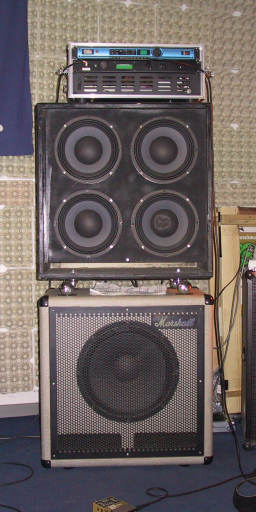
As a start i had a Marshall 1550 from the IBS series, a single 15" speaker cabinet equipped with the Celestion Sidewinder S15-250 which was soon found to be lacking the amount of treble i wanted. It would cover the lower frequency ranges, though. Temporarily i ran that speaker with a Laney 150 watt amp. Please don't ask anything about the Laney - i simply hated it with its noise and its handling.
Costs including a 4*10" additional cabinet should not exceed 400 euros ( about 450 $ ) . I first spent 200 euros on buying 4 Eminence Gamma speakers and installed them in a housing which was stackable with the 15" . Smaller gigs can be managed with the 4*10" alone.
Power Amplifier
---------------
Car power amplifiers in the 2* 200 - 300 Watt range can be found on internet auctions and i purchased a Magnat 480 Classic for 35 Euros. The PA is well build, sturdy and has quality connections. A switch allows to bridge the amplifiers for a maximum power of 2 * 240 watt. One channel is fed into the 15" and the other channel deals with the 4*10" cabinet.
ATTENTION ! The following paragraph describes how to convert an ATX powersupply to feed the Bassalizer. This deals with opening and tampering inside a dangerous unit ! If you have no experience with that, ask an expert ! There's risk to your live !
Now this PA draws a current of about 45 to 50 Amps on a 12 volt line, we have to find a power supply which is able to deliver this current cost effective and silent. It should also have good stabilization characteristics. Fortunately all these parameters are combined in the Switching power supply units for modern PC's. A standard 600 or 700 watts PSU can easily deliver the required current if a way can be found to add the 5 volt current to the 12 volt path. The following diagram shows a typical rectifier and choke section :
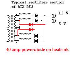
An additional power diode taps the 5 volt line before the choke and adds up to the 12 Volts line. Use a fat 30-40 Amps double diode here. Fortunately the voltage here exactly fits the 12 Volts. The rest of the power supply is unchanged. Sometimes it might be necessary to provide a load on the 5 volt line. If needed, add a 6 volt bulb as power indicator or something. I now unsoldered the unneeded voltage connections from the PSU and bundled ten cables each for the ground and the positive 12 Volt supply. The power supply is activated through a small switch which grounds the control line.
The PSU amounted to 30 euros which means the PA section was covered with 65 euros.
Housing
-------
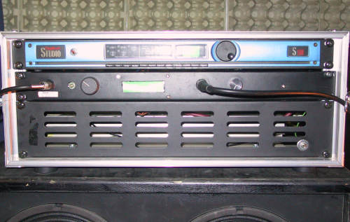
This is great news and i spent another 66 euros for a 19" rack with 4 height units, front and rear cover removable. The lower 2 HU's will be taken up by the PA section and the 2 upper sections are for the preamp and an addtional effects unit. I ordered a grilled 2 HU blind plate and one with a single height unit. The grill is used to cover the PA section, the blind plate will be the front plate for the preamp.
Effect Processor
----------------
I purchased a used Digitech S-100 for 40 euros, a 1 HU MIDI controllable stereo effects processor. The S-100 also features a parametric EQ which i use to suppress the 240 Hz 'rumbling' frequency. This frequency is mostly responsible if your bass sounds like a badly tuned Low Tom. Try to find an EQ and kill that frequency, you will not regret it :D
Ok, if we include the Digitech in the calculation we're now standing at 371 euros.
the blind/grill plates cost another 5 euros. If you have to purchase all components for the preamp you will exceed my budget, but i had all the remaining parts in my shack.
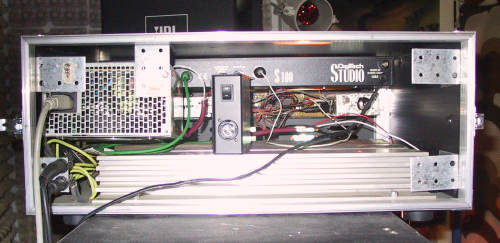
A look from the rear. I know its looking messy but i had to finish the system pretty soon back then because the former amp had to go. The DI box is inserted between effect out and master volume. Any mixer can tap the processed signal here without being affected by the master volume pot.
Preamplifier
------------
The Preamplifier is the central part of the Bassalizer and currently again subject to improvement. It features 8 storable sound configuration banks to store volume and 4 sound settings per bank. Each bank also holds 'patch' info which is used to couple 4 sound engines for either biamping , series and parallel connections inside the engines. It is therefore possible to store completely different engine configurations.
The 'first generation' Bassalizer uses 2 LM1083 stereo audio controllers. The LM1083 is controlled by 4 analog voltages each. A TDA 8444 8-channel D/A converter chip provides the control voltages to the audio chips. Each chip can be controlled for volume, balance, treble and bass.
The microcontroller section is based on the AT89S52 and features a rotary controller with push button to select , change and store bank values. A standard 1*16 LCD based on the HD44780 interacts with the user. The external footswitch is connected via a standard 1/4" jack. The whole preamplifier is powered by the 12 Volts power supply.
A picture showing the Preamplifier . From left to right there's the input amp containing the tube and the HV generator. In the middle mounted directly on the front panel is the uP board and to the right is the analogue box. The DIN plug is for MIDI to the effect processor and the purple cables on the right are the insert and line out cables.
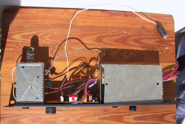
I know cabling is a mess and my next system will hold all the components in better housing. But the decision to use a tube preamp was made later when a first try with a FET input stage was discarded. I also had some pressure to finish the system back then.
Tube section
------------
A tube preamplifier in a bass system has some great advantages and will easily outpass any semiconductor solution:
* single stage already provides line level and more
* noise is neglectable
* dynamic performance is unsurpassed. This amp will eat 1 volt on the input and still not clip.
* input impedance perfectly matches instrument
The chosen circuit is the cascaded double triode, also known as 'SRPP' stage - probably one of the best preamplifier designs for tubes ever:
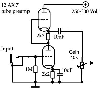
Basically this is a 'no comment' stage because of its superior performance. But it requires a supply voltage of about 300 Volts . The solution was to use a DC-DC converter from a photoflash circuit. These converters can generate a few miliamps in the required voltage range and suffice to drive the tube. Heating the valve is done directly through the 12 Volt power supply.
EQ section
------------
Flexible sound configuration requires a digitally controlled EQ and volume control. There are several solutions :
* The LM1036 is a DC-controlled tone, volume and balance control. The control voltages are in the 0-5 V range and can easily be generated with a D/A converter. The LM1036 also generates the appropriate reference voltage.
* Directly use a uC controlled Audio Processor, like the TDA7439 with 3 EQ bands. The Bassalizer Mk.II makes use of 2 of these chips. This project suffers from an oscillating stage at the moment.
* Use a DSP like the TMS320xx/TAS30xx or the Motorola DSP56001. Probably the best solution, but requires a developer system and DSP algorithms.
Bassalizer Mk. III uses a TAS3208 TI DSP for audio applications and an ATMega to control it. It features a dual 7-Band EQ and engine patching comparable to the Bassalizer Mk. I. This project is now finished and is presented here: Bassalizer Mark III
However, the current system has been running reliably for four years now, except a loose capacitor. A bass top is always subject to vibrations from the speakers and requires a rugged design :-P Here now the audio engine design:
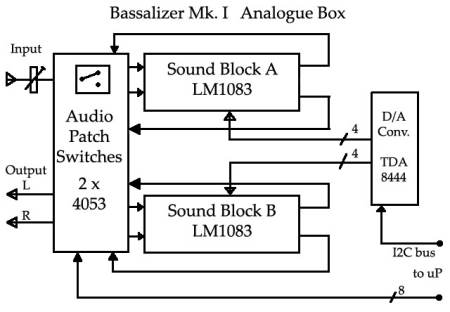
The main EQ blocks are surrounded by a set of analogue switches of the 4053 type. These switches can switch the sound blocks into parallel or serial mode and allow a quick change in the sound configuration. The sound blocks have slightly different tuning circuits for treble and bass so that a larger range of frequencies is covered . Sound Block A is mainly configured to drive the 4*10" cabinet and thus is tuned higher than Sound Block B which drives the 15" speaker.
The D/A converter is of the TDA 8444 type and supplies 4 voltages per Sound Block for Volume, Treble, Bass and Balance. It is controlled via the I2C bus from the processor. The analogue switches are controlled by a separate 8-bit port. All parameters are stored in EEPROM and can be changed on the fly.
Not shown in this diagram is the output amplifier, the master volume control and the insert points for the external effect processor. The output amplifier prooved necessary as the LM1083 chips can't provide more than approx. 300 mV. The amplifier is a standard dual opamp circuit wired to a gain of 5 - enough to drive the PA.
Microcontroller
------------
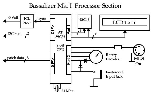
The chosen processor is an AT89S52. It has a sufficient number of port pins to drive the peripherals and nearly enough interrupt sources for fast user interaction. It also allows quick 'in-field' reprogramming through its ISP interface. The LCD in the 'first generation' Bassalizer is a 1*16 digit display which is driven in 4-bit mode. This will save some wiring and is fast enough. Parameters are controlled through a rotary encoder and its pushbutton - pressing the button will cycle through the parameters and turning the encoder changes values. Pressing the button longer will store the current bank in EEPROM. All input routines are interrupt driven for quick user feedback. The footswitch doesn't generate a separate interrupt but is wired-or with the encoder button and pulls an extra line to ground. The irq routine then determines the source of the interrupt and acts accordingly.
An 8-bit port (Port 0) is used for the audio patch switches. Port 1 is wired to the LCD and the 93C46 EEPROM. Port 3 is used for the MIDI interface, the rotary encoder and the footswitch. Port 2 provides the I2C bus and a 40 khz signal on one of its pins. This signal is used to pull the frequency of a small DC-DC converter with the ICL7660 out of audible range. This DC-DC converter provides a negative supply voltage to the analogue switches and to the output amplifier and is located on the CPU board.
To give you an idea of the different patch configurations here's a schematic on what engine combinations are possible:
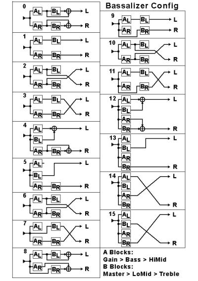
Have fun !!
Email me for Questions and suggestions.