Even if the old ( Mark I ) Bassalizer did a good job for 5 years improvement of its preamplifier section still seemed possible and the availability of a new low cost DSP evaluation kit from Texas Instruments made it possible to develop a DSP-driven preamplifier.
The TAS3208 EVM-LC module consists of the TAS3208 signal processor with the necessary peripherals to construct a self-contained amp with I2C control . The TAS3208 has a 48 bit data path and is able to execute 5 instructions simultaneously at a clock frequency of 135 Mhz, perfect for audio applications. The board is powered either through USB or an external 5Volt supply. The USB interface is used for programming the onboard EEPROM. During power-up, the contents of the EEPROM is downloaded into the TAS3208 and executed. Control of variables is done through a two-wire interface ( I2C ) and done by the front panel processor.
Here's a picture of the new Bassalizer front:
The TAS3208 board has 3.5mm jacks for in- and output. The signal box also contains the well-know tube preamp with a 12AU7 in SRPP configuration and the 300 volts HV generator. Changing the 12AX7 to a 12AU7 was done due to the lower gain of the new tube and a decreased output impedance which has its advantages for driving the DSP input stage:
Here's a picture showing the Bassalizer Mark III from the rear:
from left to right : Master volume pot with in- and output RCA plugs,footswitch jack, panel processor, signal box.
The panel processor is an ATMega328 controlling the SPI-driven graphics LCD, a rotary encoder with pushbutton, the footswitch for changing sound banks and of course the I2C controls for the DSP processor. Its internal EEPROM contains the sound bank data. The LCD is a backlit DOGM132-5 with a resolution of 132*32 pixels. Handling is more or less similar to the older Bassalizer: Rotating the wheel does change values and pushing the button will advance through the parameters. A longer press will store the current bank.
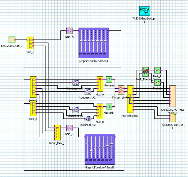
Here now is the process flow for the DSP as seen in TI's CodeComposer:

On the left the input from the tube preamp. The signal then passes through a set of splitters and switches to configure the dual engines. Variable gain blocks adjust the input level. The signal then passes through the 7-band equalizers and optional loudness filters.The output master controls are followed by a limiter to avoid distortions by an overdriven DAC. The output is routed to two of the three analog outputs and the SPDIF digital output. The third stereo output delivers a peak detector output which is connected to the ADC of the panel processor for VU display. All of the DSP parameters are controlled through the 2-wire interface.
Have fun !!
Email me for Questions and suggestions.
